Gyroscope physics
One of the evergreens of classical mechanics demonstrations is the behavior that can be elicited from a gyroscope.
The word 'gyroscope' was coined by the french physicist Foucault. Foucault was active in optics, in the manufacturing and testing of lenses and mirrors, in the chemistry of photography, and he did research in electromagnetism. Today he is mainly known for the pendulum setup that is called 'Foucault pendulum'.
Free spinning gyroscope

In 1852 Foucault used a gyroscope to demonstrate the Earth's rotation. The gyroscope wheel is in a double-axed gimbal mount, so that the force of gravity acts on the wheel's center of mass, and no torque is acting on the wheel. Without torque to change its direction of motion a spinning gyroscope wheel will remain pointing in the same direction.
An object left to free motion will move in a straight line. The spinning of the gyroscope wheel can be thought of as combining two oscillations, perpendicular to each other. Each of these oscillations remains on the same line, making the plane that is defined by the two perpendicular lines a stationary plane. Hence the spin axis, perpendicular to the plane, keeps pointing in the same direction.
A gyroscope subject to torque
I will use the following naming convention: I will take the word 'gyroscope' to refer to the assembly of gyroscope wheel and all of the suspension mount together. I will call the spinning mass - usually a disk-shaped object - the 'gyroscope wheel'.
Bicycle wheel
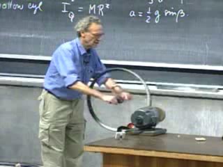
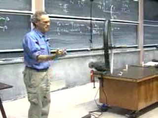
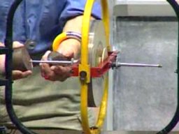
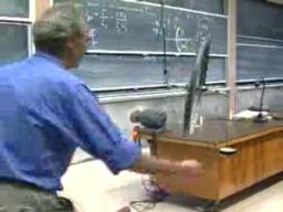
The image shows a demonstration from a lecture by professor Walter Lewin. Using an electric motor he spins up a bicycle wheel to a hair raising velocity, and then he hooks up the wheel to a rope suspended from the ceiling. Initially, walking up to the rope, he supports both ends of the axle. When the rope takes the weight the wheel starts precessing.
|
|
|
Picture 2, picture 3, image. Source: MITopencourseware physics 8.01, Youtube video 35:30 | |
Gyroscope
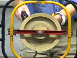
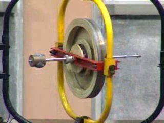
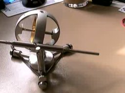
Pictures 4 and 5 show a gyroscope in a multi-axed gimbal mounting. The yellow frame enables swivel, the red frame enables pitch. The wheel's bearings rest on a fixed axle that extends out of the red frame.
Notice especially the instant at 47:10, when professor Lewin happens to manipulate the yellow frame. The turning of the yellow frame is transmitted to the gyroscope wheel, and just for a moment you can see how the gyroscope wheel responds to that.
|
|
|
Picture 4, picture 5, image. Source: MITopencourseware physics 8.01, Youtube video 46:00 | |
The demonstrations by professor Lewin are so vivid because he spins the wheels so fast. (You definitely shouldn't try that at home.)
The purpose of this article is to show how to understand the behavior of the gyroscope in terms of the laws of motion.
Naming conventions
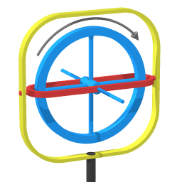
Image 6 represents the gyroscope in the demonstration by professor Lewin. To emphasize the different components I gave them contrasting colors.
- Roll : spinning of the blue gyroscope wheel
- Pitch : tilting of the red frame
- Swivel : rotation of the yellow frame.
The swivel axis has the least freedom; the swivel axis is fixed relative to the ground. The pitch axis is always perpendicular to the ground, as it is constrained by the yellow frame. The innermost frame, the red frame, has the most freedom. So the roll axis can point in any direction. 'Roll' has been defined as spinning of the wheel. That means roll is defined relative to the wheel.
Internal links:
The following two articles provide good preparation for the subject of gyroscopic precession:
Angular momentum of orbiting objects When in a rotating system mass moves towards/away from axis of rotation: the work done changes the angular velocity.
Coriolis flow meter The operating principle of Coriolis flow metering is the lagging behind and pulling ahead effect of moving towards/away from axis of rotation.
Sustained precession
Forces and motion of a precessing gyroscope
All wheel mass moving through the shown quadrant is moving towards the swivel axis
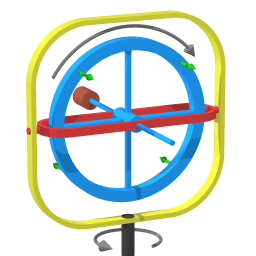
Image 7 depicts the gyroscope when it is precessing.
The brown cylinder represents the weight that has been added on one end. If the gyroscope wheel would not be spinning the weight would pitch that end all the way down.
In the demonstration the spin rate is much faster than the precession rate, so it's natural to think of the overall motion as a composition of two perpendicular uniform rotations: rolling and swiveling. Image 7 shows two black arrows to depict the wheel's two component rotations.
Quadrants
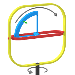
Rather than trying to focus on a section of wheel, trying to track it, it's clarifying to look at how the parts of the wheel move through successive quadrants. Image 8 shows one such quadrant. With the wheel spinning wheel mass moves through that quadrant.
Motion towards the swivel axis
In the quadrant shown in image 8 the mass of the wheel is moving towards the swivel axis, and so is the mass moving through the diagonally opposite quadrant.
We have that when circumnavigating mass is pulled closer to the axis of rotation (the swivel axis in this case), that mass tends to pull ahead of the overall circumnavigating motion. The green arrow depicts that tendency.
Motion away from the swiveling axis
In the other two quadrants the mass of the wheel is moving away from the swivel axis, so the mass in those quadrants tends to lag behind the overall swiveling motion.
Pitching
The four green arrows in image 7 illustrate that the effects from each of the four quadrants combine to a pitching effect. The effects from each of the four quadrants add up: they reinforce each other into a single pitching effect.
In particular, this explains why a gyroscope wheel has its strong response at a 90 degrees angle. It's at 90 degrees because of the overall symmetry: the contribution of each of the four quadrants is the same, therefore the response can only be at that 90 degrees angle.
The response of a spinning gyroscope wheel
48:00 into the video, only seconds away from adding a weight.
Image 9 is at 48:00 into the video.
Let me go step by step over what happens at the exact instant that the weight is added.
- When the weight is positioned onto the axle rod the force that it exerts starts to pitch the gyroscope wheel. That is: the initial response is pitching motion
- The gyroscopic response is response to motion: pitching motion leads to swiveling.
- In the absence of a force the swiveling motion would lead to pitching up. However, in this case tendency to pitch up is expended to act in opposition to the force that led to the initial pitching down.
- The gyroscope settles into a sustained dynamic configuration, neither pitching up nor pitching down.
Usually the demonstrator will guide the onset of precession motion, retracting his/her supporting hand only when he/she feels that the gyro wheel has arrived at the precessing velocity where the external pitching force is fully counteracted.
When the demonstrator doesn't do a guided onset but instead releases instantly the resulting motion is a combination of gyroscopic precession and nutation. All demonstrators develop the habit of guiding the onset of gyroscopic precession, no doubt because nutation component, when present, makes the demonstration look less clean.
Understanding of nutation is crucial, but unfortunately demonstrators are in the habit of smoothing out precession onset, thus keeping nutation out of sight.
Self-adjustment
38:20 into the video. Faster precession when extra torque has caused further pitching down.
The process of settling into precessing motion is a process of self-adjustment: the final precessing rate is the rate of precession that keeps the wheel from pitching down further.
Picture 10 (38:20 into the video) shows what happens when more weight is added. The added weight increases the torque, so the wheel pitches down some more. The motion of pitching down causes the precession to speed up.
Note that professor Lewin increases the torque load gingerly. An uncontrolled drop of the extra weight would add a nutation. See the nutation section further down in this article.
Friction
If the demonstration is allowed to play its course then friction will keep reducing the wheel's spin rate. The wheel will progressively pitch down, with corresponding increase in precession rate. (Actually, as the wheel pitches down the torque from gravity becomes smaller, making the requirement for precession lower.) Eventually the spin axis will be practically parallel to the direction of gravity.
What the torque is and isn't doing
Precession will only start if a force sets it into motion, but once precession is going it simply goes on. For comparison: the example of circular motion, sustained by a centripetal force. The centripetal force doesn't cause or sustain the speed; the centripetal force causes/sustains the circumstance (the circular shape of the trajectory) that allows the speed to continue. Likewise, once there is a uniform precession going the torque is neither causing nor sustaining the precession. The torque sustains the dynamic configuration in which precession can exist.
Precession decay
Spring tension preventing further pitching.
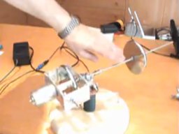
Next, let me discuss what you see in the following YouTube gyroscope video, which according to the profile information has been uploaded by a user named Glenn.
You can see how Glenn is swiveling the gyroscope wheel and in response the gyroscope wheel is pitching up and down. There are two cross-arms, and two helical springs act to keep those cross-arms level. At 20 seconds into the video Glenn starts a steady precession.
Without the springs the gyroscope wheel would pitch over completely, to the point where the spin axis coincides with the swivel axis. (That point is the point with lowest potential energy.) As the cross-arms pitch a spring is stretched until the point is reached where the tension matches the tendency to pitch over.
Air friction is slowing down the gyroscope wheel, as friction cannot be eliminated entirely. As the spin rate decays the tendency to pitch decreases. This allows the stretched spring to pull the cross-arms to a more level position. The pitching motion of leveling out reduces the existing precession rate. When the cross-arms have leveled out completely the precession has been nullified.
Nutation
A jolt induces nutation.
A Youtube gyroscope video uploaded by Adolf Cortel shows nutation. At one minute into the video Cortel gives a jolt to the system. That induces a nutation on top of the precession. The cycle of nutation proceeds as follows: pitching down is converted to swiveling clockwise, which is converted to pitching up, which is converted to swiveling counterclockwise, which is converted to pitching down, and so on. The result is that the nutation traces out a cone with respect to the steady precessing motion.
Nutation is like circular motion in the following way: it cycles around a point of lowest energy. If there is damping then the nutation spirals in, settling on the point of lowest energy.
Mathematical discussion
This mathematical section is for corroboration. The result matches the result that is calculated with other mathematical means (involving Euler angles).
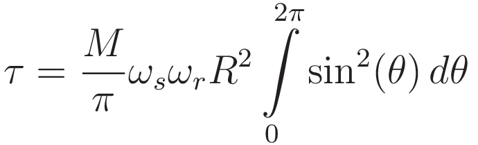
The combined effect of the four quadrants can be calculated by integrating around the wheel, which means integrating over an arc of 2π radians.
The purpose of the calculation is as follows: when the gyroscope wheel is precessing (as depicted in image 7) the precession gives a tendency to pitch. The derivation finds the corresponding torque.
The following integration applies the usual simplification that the gyroscope wheel is treated as if all of it's mass is on it's circumference. An actual wheel can't be like that of course, since you need spokes. But the mass of the spokes is much less than that of the rim, so for a first approximation the mass of the spokes can be neglected.
| Angle around the circumference of the wheel | θ |
| Force in tangential direction | Ft |
| Torque | τ = Ftr |
| Rolling rate | ωr |
| Swiveling rate | ωs |
| Total mass | M |
| Mass per unit of arc | M/(2π) |
| Velocity component towards/away from central axis | vr = ωrsin(θ)R |
| Distance to pitch axis | sin(θ)R |
| Tendency to pull ahead/lag behind overall swiveling | F = -2mωsvr |
Let me go over the entries in the above table.
- Angle around the circumference of the wheel. Let parallel to the pitch axis be θ = 0
- The 'force in tangential direction' refers to a force that tends to pitch the gyroscope wheel.
- The 'mass per unit of arc'. The units of arc are radians here. Total circumference is 2π radians, hence the mass per unit of arc is M/(2π)
- 'Velocity component towards/away from central axis'. At the points where the wheel rim is farthest away from the swivel axis the velocity component in radial direction is zero. The radial velocity is maximal when θ is 1/2π and 3/2π.
- 'Distance to pitch axis'. Distance to the pitch axis is maximal when θ is 1/2π and 3/2π
- 'Tendency to pull ahead/lag behind overall swiveling' The expression for this is derived in the Appendix F=-2mωv
These elements together give the following integral over the full circumference of the wheel (the minus sign is dropped because only the magnitude of the effect is needed):
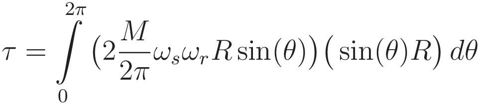
Rearranging, and moving factors that are not a function of θ outside the integration:
We have:
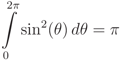
Combining (2) and (3) gives the result:
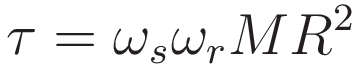
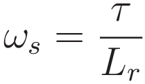
When the spinning rate of the gyroscope wheel is far larger than the precession rate the overall angular momentum L of the gyroscope wheel is practically identical to the angular momentum of the spinning motion Lr, which is given by ωrMR². Therefore to a good approximation (4) can be simplified to:
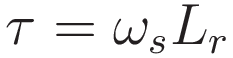
(5) gives the tendency to pitch that arises from the combination of rolling and swiveling gyroscopic precession. It is proportional to the swiveling rate ωs and the angular momentum Lr of the rolling gyroscope wheel.
Expression (5) matches the expression given in textbooks, where it's usually derived in the following form:
Appendix - Derivation of F=-2mωsvr
Repeat of image 8
The derivation below deals with what is illustrated with image 13. The rolling moves the parts in the shown quadrant closer to the swivel axis. And the question is: how large is the tendency to pull ahead of the general swivel? To obtain the answer to that I go through two stages:
1. First I answer the question: if circumnavigating point mass is pulled closer to the axis of rotation with a particular radial velocity, how large will its tangential acceleration be?
2. Then I turn that around: the amount of force that is necessary to prevent angular acceleration is given by tendency to accelerate multiplied with the mass.
Two weights connected to pistons. Hydraulic machinery (not shown) pulls the weights closer to the center of rotation, causing angular acceleration.
Stage 1., the case where angular acceleration is not prevented; angular momentum is conserved.
(The animation can be halted by clicking on it; clicking on it swaps the animation with a still picture.)
For this assessment it is not necessary to keep track of the motion component parallel to the swivel axis. We simplify to the motion component in the plane that is perpendicular to the swivel axis. Picture 14 shows such a planar case. The advantage of simplifying to the planar case is that scalar notation is sufficient
The goal here is to obtain an expression for acceleration in the direction at right angles to the instantaneous radial distance.
The steps (7) to (11) arrive at that as follows: constant angular momentum means that the derivative with respect to time of the angular momentum is zero. That is sufficient to obtain an expression for acceleration.
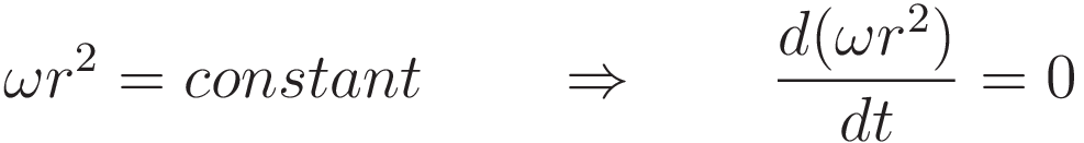
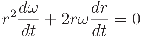
Differentiating the expression for the angular momentum:
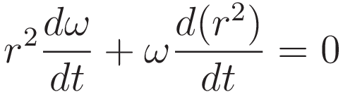
Using the chain rule to obtain an expression in terms of a factor dr/dt .
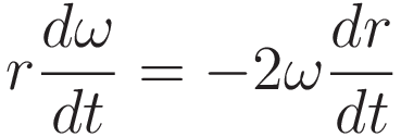
Dividing by r, and rearranging
Let at denote acceleration tangent to the circle of the current radius r, hence perpendicular to the instantaneous radial direction. We have that r(dω/dt) is acceleration perpendicular to the instantaneous radial direction. So on the left hand side we substitute at for r(dω/dt)
Let vr denote velocity in radial direction. So on the right hand side we substitute dr/dt with vr
The result:
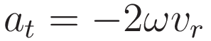
This expression gives the tangential acceleration that occurs if there is no torque present.
Multiplying both sides with m gives the corresponding force:
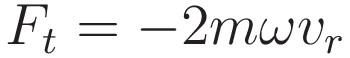
The above completes stage 1. of the two stages. Stage 2. is to see that if at every point precisely that force is exerted (in the opposite direction) then change of angular velocity is prevented, and the rotation rate ω will remain the same.
Referring back to picture 7, where the green arrows represent the tendency to pitch when the gyro wheel is rolling and swiveling. At every point around the circumference of the gyrowheel the pitching effect is different. To obtain the total pitching effect an integral is required; integrating around the circumference of the gyro wheel.
Sources:
- Harold Crabtree An elementary treatment of the theory of spinning tops and gyroscopic motion (1909)
- Svilen Kostov, Daniel Hammer It has to go down a little, in order to go around (2011)

This work is licensed under a Creative Commons Attribution-ShareAlike 3.0 Unported License.
Last time this page was modified: December 29 2023